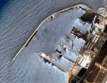
PROJECT: Design verification of a dual high speed railway lines launched bridge superstructure (using detailed analysis), in section Tithorea - Domokos at Ch 13+359 with a total length of 299m, seismically isolated
CLIENT: J/V AKTOR S.A. - J & P - AVAX S.A.- TERNA S.A.
CONSTRUCTION: J/V EURARCO SA – ERGONET SA
DESIGNER: T.TSIKNIAS & PARTNERS SA
BRIEF DESCRIPTION:
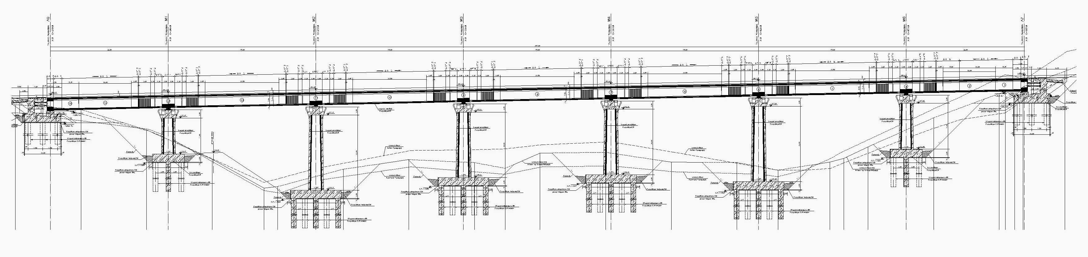
The bridge structural system is a single cell box cross section continuous beam with typical spans 45m long having total length 299m, a curve in plan. The bearings are friction pendulum spherical bearings rest on single cell box piers up to 28m high. The foundation is on piles.
IN PARTICULAR:
The superstructure consists of seven continuous prestressed spans with 45m central spans lengths. Superstructure rests on piers through seismic isolation devices.
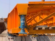
The seismic isolation system is based on the use of movable spherical bearings (friction pendulum bearings, FPS) and hydraulic viscous dampers that act as dynamic locking devices (shock transmission units) for service loads. All pier bearings are able to move on both horizontal directions, while the abutments, due to railway line requirements, have restrains in the transverse direction. Maximum vertical load of bearings 25MN
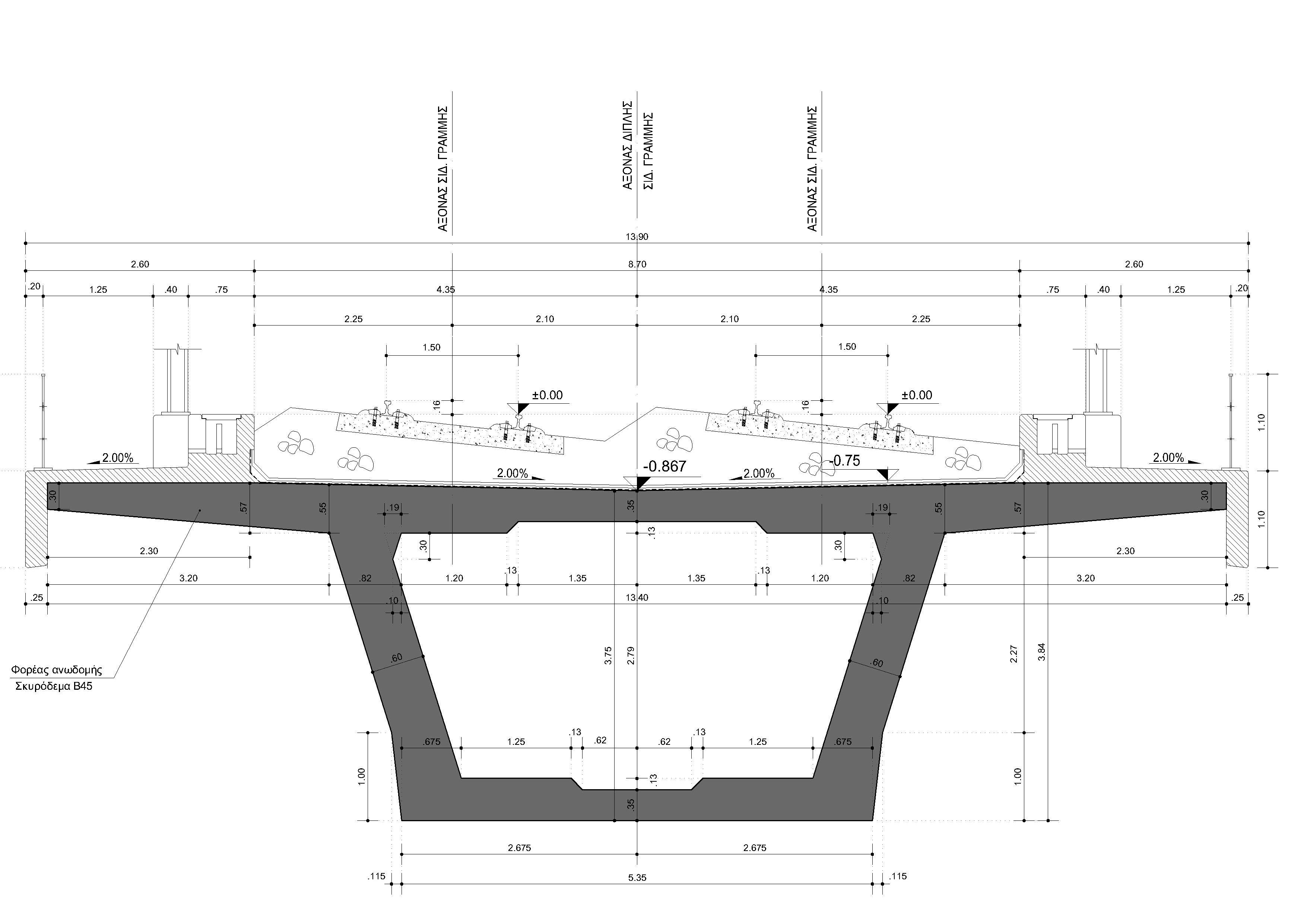
The bridge superstructure cross section has the shape of a single cell box girder with structural height 3.75m and total width, with overhangs, 13.90m
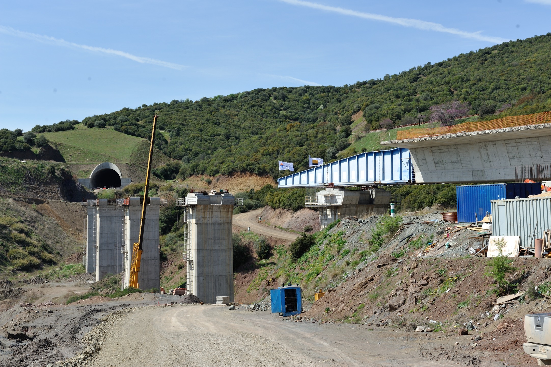
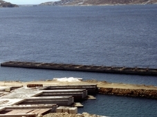
Launching was in typical sections of 22.5m using as tip a steel cantilever 29.5m long. The bridge is curved in plan R = 750m.
The piers consist of a single cell box with cross section 4.0x6.0m at the level of superstructure supporting beam with the dimension 4.00m (towards the span of the bridge) to vary increased by height with a slope 1 / 70. The wall thickness is 50cm and superstructure supporting beam height is 2.50m.
Pile caps are 2.50m thick, built on bored piles with a diameter of 1.50m.
DESIGN VERIFICATION:
The superstructure design verification was triggered as a result of a lengthy construction halt due to the financial problems that the previous contractor company was facing forcing it to abandon the construction process. The constructed part of the bridge superstructure was only the first two segments, having a total length of 9.75+16.00=25.75m. When the new contractor installed, pretension stands, as well as pretension tubes, (left without tension and grout) found to have extensive oxidations.
A detailed report of site foundlings was prepared along with conclusions and proposals, completed by a following laboratory examination for the pretension steel oxidation degree (prepared by The Metal Structures laboratory of Civil Engineering School, National Technical University of Athens, under proff. Ch. Gantes). This examination had the same conclusions with our site report i.e. the replacement of pretension steel strands.
The replacement of the second phase stands (the parabolic ones) didn't face a special technical problem although some of the anchors were obstructed by the steel nose (cantilever), to be replaced after the end of launching. This wasn't the same with linear strand expansion anchors already cast in concrete at joint between constructed segments.
Expansion anchors uncovered using water jetting following a procedure we proposed and approved by the owner technical staff. Given the ability to remove and replace the stands, the design verification had to examine the effect in the longitudinal superstructure forces, during launching and operation, of:
-
the increased friction between the new strands and cast in concrete tubes,
-
the construction time sequence change to structure stresses. Construction sequence was previewed, by the original design, as one week between successive segments and this one had change to about 5 years between segment 2 to 3 while the structure has being left supported between abutment and a temporary pier with half of the required pretension applied.
After the detailed verification conclusions the procedure had:
-
to determine the minimal changes in structure geometry that would be able for the superstructure to comply again with the requirements of design standards.
-
to include these changes in design analysis
-
to update design construction drawings where necessary.
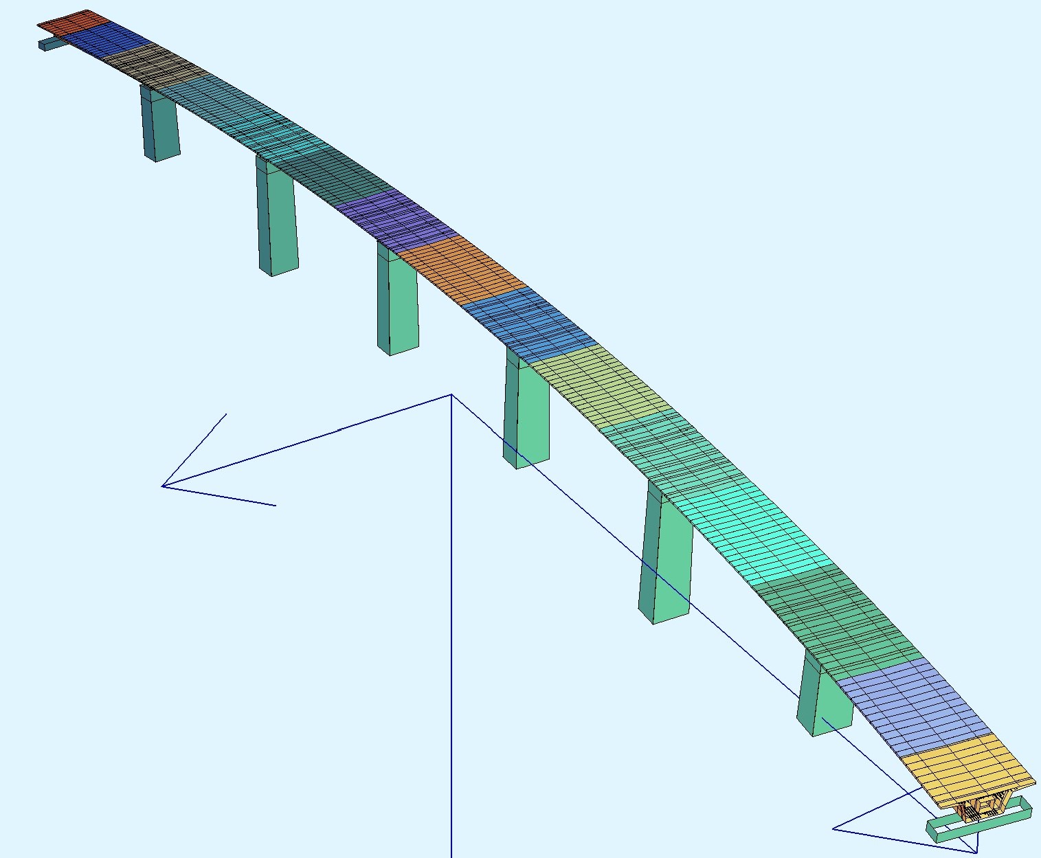
The design verification included a very extensive technical description for the structure modelling, analysis flow, loadings and results evaluation as well as the graphical presentation, in colour, of the calculated forces, combinations, stresses, reinforcements etc.
The design was conducted in two related phases:
A' Phase: Launching.
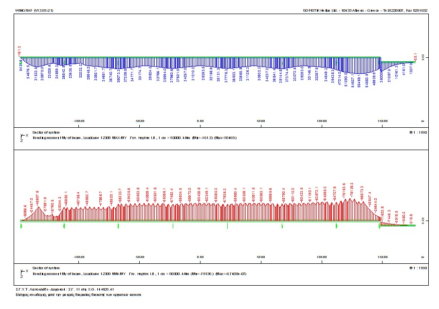
The analysis was following the construction phases and movement of the deck. For that purpose the development of a program code in lisp (approximately about 6700 lines of code producing additional 9900 lines of input data) was necessary to provide input / modification data of a continually modified bridge structural system in the analysis program (sofistik). By that means analysis was monitoring the movement of superstructure (with steps of about 3.75m) during launching. In each of these positions, the superstructure was loaded for dead load, bearing tolerances and temperature difference (except those for prestressing losses and creep, per launching phase) producing envelopes of structure internal forces. Number of independent loading cases (support tolerances - temperature) examined only during launching was 2133, in a total of 104 structural systems developed to model the movement.
B' Phase: Operation in service
The second associated phase was considering the superstructure to its final position, with the final prestressing forces, service and other possible loads during operation.
The bridge is under construction.
Design year: 2016-7
Design standards: DS804, Greek Earthquake Design Standard